


Laser Technologies of one Chinese company
Лазерные технологии одной китайской компании
Oleg Figovsky
The leading countries on laser technologies are USA (491 patents for inventions). But more patents have the one is Chinese Han’s Laser Technology Industry Group Co., Ltd, a public company which was established in 1996, has now became the flagship of Chinese national laser industry and the world’s famous laser equipment. Nowadays, the fundamental infrastructure is not limited to repair the road, build the railway, connect the electrical cables, more include the water and electricity, cultural entertainment instruments, photovoltaic and other new industries, the aim is to vigorously construct the socialist spiritual civilization that is based on the adequate food and clothing of the people. This company has now more than 5600 patents both any classical inventions or commercial marks in the field of laser technologies and I would like to introduce only last ones.
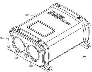
The patent US2023146823 describe a handheld laser-based vehicle speed measurement device incorporating on-board data storage with GPS, compass, excess panning detection, and voice recognition technology as well as, recording minimum and maximum speeds of a plurality of vehicles along a roadway and calculating the 85th percentile speed (see below)

First page
clipping of US2023146823 (A1)
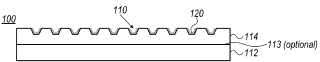
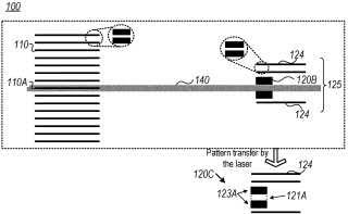
The patent US2023129519 describes pattern transfer sheets and methods are provided for printing paste patterns (e.g., thin fingers) with a high aspect ratio and for increasing throughput in pattern transfer printing.
Trenches in the pattern transfer sheets, that are configured to be filled with printing paste and to enable releasing the printing paste from the trenches onto a receiving substrate upon illumination by a laser beam—are coated internally by a coating configured to disintegrate upon the illumination. The coating is configured to enhance the releasing of the paste—increasing throughput and printing accuracy. The receiving substrate may be cleaned after paste deposition by removing disintegration products of the coating therefrom. Alternatively or complementarily, laser absorbing dye may be mixed into the printing paste to facilitate its release from the trenches.
First page
clipping of US2023129519 (A1)
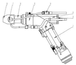
The invention ZA202212376 relates to the field of laser cladding, in particular to a handheld laser cladding head device which comprises a handheld gun body, a focusing mirror mounting seat, a focusing mirror, a powder distributing block, a protective mirror module, a connecting column, a hard alloy pipe and a powder feeding nozzle. The focusing mirror mounting base is fixedly connected to the handheld gun body, the focusing mirror is mounted in a hole of the focusing mirror mounting base, the powder distributing block is fixedly connected to the handheld gun body, the protective mirror module is fixedly connected to the handheld gun body, the powder feeding nozzle is connected with the protective mirror module through the connecting column, and the hard alloy pipe is connected with an inner hole of the powder feeding nozzle in an interference fit mode. The device is small and exquisite in structure, flexible to use, stable and reliable to operate and capable of bearing high-power laser; therefore, the laser cladding operation can be quickly and conveniently carried out on some irregular parts or special parts of the parts; and the market blank of handheld laser cladding is filled in the laser cladding market.
First page clipping of ZA202212376 (B)
The invention CN115786909 provides a laser cladding repairing method for a guide, which comprises the following steps of: constructing a guide three-dimensional model to be repaired by adopting a three-dimensional scanning technology and a three-dimensional modeling technology, performing three-dimensional fusion on a guide standard component and the guide to be repaired to obtain a repaired three-dimensional model, and dividing the repaired three-dimensional model into a plurality of cube blocks, the repairing three-dimensional model is completely covered with the multiple cube blocks, and the valve opening degree of shielding gas and powder feeding gas is set by

First page
clipping of CN115786909 (A)
designing power control of a laser cladding device, the use amount of cladding materials and power control of the laser cladding device when different blocks are repaired, so that accurate repairing is achieved.
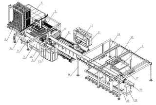
The invention CN115771028 relates to an automatic machining line for sheet metal forming and a machining technology thereof, and belongs to the technical field of machining. The automatic machining line comprises an automatic material warehouse used for storing sheets, a movable discharging trolley is arranged below the automatic material warehouse, and a feeding and discharging device, a conveying belt and a gantry frame are sequentially arranged on one side of the automatic material warehouse; a laser cutting machine is arranged on the rear side of the automatic material warehouse, a feeding and discharging mechanical arm is installed on the feeding and discharging device, a stacking carrying mechanical arm is arranged on one side of the belt conveyor, bending robots are arranged on the two sides of the front end of the conveying belt, bending machines are arranged on the outer sides of the bending robots, and a carrying mechanical arm and a discharging mechanical arm are arranged on the gantry frame. A positioner and a welding robot are further arranged below the gantry frame. The machining line is used for machining the plate, the whole machining process including discharging, cutting, bending and welding is automatic, and the adjacent working procedures are automatically connected.
First
page clipping of CN115771028 (A)The whole machining line is high in automation degree, and manpower and material resources are greatly saved.
The embodiment of the invention CN115740984 belongs to the technical field of laser cutting, and relates to a laser cutting control method which comprises the steps that a to-be-cut contour of a laser cutting plate is obtained; acquiring first process layer information corresponding to the contour to be cut; determining a cutting process of the to-be-cut contour according to the first process layer information; and laser is controlled to cut the plate according to the cutting process. The invention further provides a laser cutting control device, computer equipment and a storage medium. According to the embodiment of the invention, in the laser cutting process, the cutting process can be determined according to the specific condition of the plate. Specifically, in the cutting process, the cutting technology can be determined for each to-be-cut contour, local film spraying machining of the plate is automatically achieved, and meanwhile the laser cutting efficiency is improved.
The embodiment of the invention CN115722805 belongs to the technical field of laser processing, and relates to a laser processing method and a laser processing system using visual imaging. The laser processing method using visual imaging comprises the following steps that a product is placed on a processing platform, and a to-be-processed area of the product is located in a visual imaging range of a visual imaging module; shooting an image of the to-be-processed area through a visual imaging module; the shot image is processed, and a processing drawing corresponding to the to-be-processed area of the product is obtained; and performing laser processing on the product according to the set laser parameters and the processing drawing. The problem that the relative position precision of a film material and glass is poor due to a traditional film pasting method is effectively solved, the technological process is simple, the relative precision of the film material and the glass edge is high, high-precision film pasting equipment does not need to be used, a laser product can be directly assembled, the production cost is reduced, the machining procedures are reduced, meanwhile, the prepared product is high in environment tolerance, and the production cost is reduced. The edge is smooth and fine.
The disclosed by the patent CA3182652 method for debarring and chamfering a burred sharp edge, which is defined between two transversely extending sides of workpiece, includes forming a molten pool of material on one of the sides by a laser beam which wobbles transversely to the burred edge. The wobbling amplitude of the laser beam is controlled so that the oscillating beam is prevented from being guided beyond the edge. The heat generated by the molten material is transferred to and liquefies the burrs. As the molten material cools and solidifies, it pools on the surface of the workpiece forming a raised smootcurved surface layer which chamfers the edge.
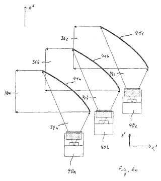
Acording the patent MX2008014559, array comprising high power laser diode comprising laser light emitters, each defining, in a direction perpendicular to direction of propagation of an output laser beam, a fast axis and a slow axis; fast axis collimating means for collimating output laser beams in fast axis direction; and slow axis beam shaping means for collimating or focussing output laser beams in slow axis direction, said slow axis beam shaping means disposed external to said high power laser diode; wherein said laser light emitters are displaced relative to each other in fast axis direction or in fast and slow axis direction by equidistant spacings, respectively; and including optical means for forming output laser beam profile in far field of all laser light emitters consisting of said fast and slow axis collimated or focussed output laser beams arranged adjacently in seamless manner in one or two dimensions with optical fill factor of about 100%.
First page
clipping of MX2008014559 (A)
The utility model according to CN218461242 belongs to the field of laser engraving machine auxiliary technology application equipment, and particularly relates to a laser engraving machine auxiliary distance measuring device which comprises an auxiliary distance measuring device body clamped on a laser adjusting and engraving machine lifting arm, the auxiliary distance measuring device body comprises an L-shaped supporting frame, and a clamping mechanism is arranged at the end of one side of the supporting frame. A U-shaped containing cover is arranged at the lower end of the supporting frame, a key-shaped groove is formed in the side edge wall of the containing cover, an arc-shaped limiting groove is formed in the portion, below the key-shaped groove, of the containing cover, a rotatable moving part is arranged in the containing cover, a lead screw mechanism is arranged in a moving plate, and a lifting plate is arranged at the front end of the lead screw mechanism. A lever indicator is arranged at the front end of the lifting plate. The laser engraving machine lifting arm control device is reasonable in design, simple in structure and convenient to machine, the lifting distance of a laser engraving machine lifting arm with a laser engraving head can be effectively and accurately controlled, the auxiliary distance measuring effect is achieved, the accuracy is improved, the workpiece forming quality is guaranteed, and the use requirement is met.
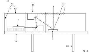
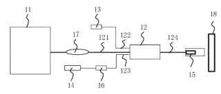
A laser projection apparatus (WO2023029945), related to the field of display technology. A laser projection apparatus (1000) comprises: a light source assembly (1), an optical machine (20) and a lens (30). In the light source assembly (1), an encapsulation housing (12) is connected to a thermally conductive substrate (11) and comprises a light outlet (121). The light outlet (121) is located on a side of the encapsulation housing (12) furthest from the thermally conductive substrate (11). A first light-emitting chip (14) is disposed in the encapsulation housing (12) and is connected to the thermally conductive substrate (11), and is configured to emit a first laser beam. A fluorescent portion (15) is disposed in the encapsulation housing (12) and is connected to the thermally conductive substrate (11). The fluorescent portion (15) is disposed at a light-emitting side of the first light-emitting chip (14) and is configured to emit, under the effects of at least a portion of the light in the first laser beam, a fluorescent beam toward the light outlet (121). An optical path guide assembly (13) is disposed in the encapsulation housing (12) and is configured to guide the first laser beam to the fluorescent portion (15). At least a portion of the light in the fluorescent beam is emitted from the light outlet (121) in a direction away from the thermally conductive substrate (11), so as to form at least a portion of the light in an illumination beam.
First page
clipping of WO2023029945 (A1)
First page
clipping of US2022390655 (A1)
According to patent US2023019668, pattern transfer sheets, methods of monitoring pattern transfer printing, and pattern transfer printing systems are provided, for monitoring and adjusting laser illumination used for transferring paste patterns from trenches on the sheets onto a substrate such as electronic circuitry and/or solar cell substrates. Pattern transfer sheets comprise, outside the pattern, (i) trace mark(s) configured to receive the printing paste, aligned to the trenches and are wider than the width of the illuminating laser beam—to detect misalignment of paste release from within the trace mark(s) and/or (ii) working window marks configured to receive the printing paste, set at specified offsets with respect to specific trenches, with different working window marks set at different offsets—to correct the effective working window by adjusting the power of the laser beam.

First page clipping of US2023019668 (A1)
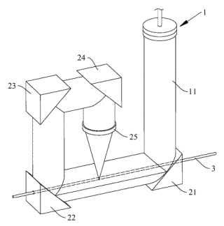
The invention CN115592260 belongs to the technical field of laser processing, and particularly relates to a micro pipe laser processing device and processing technology. The device comprises a beam-expanding hollow processing device used for processing laser emitted by a laser generator into a beam-expanding hollow light beam; the first reflecting mirror and the second reflecting mirror are oppositely arranged and located on a straight line where the conveying direction of the miniature pipe is located, the miniature pipe penetrates through the first reflecting mirror and the second reflecting mirror, and the first reflecting mirror reflects a beam-expanded hollow light beam vertically emitted to the straight line to the second reflecting mirror along the straight line; the second reflector reflects the expanded hollow light beam away from the straight line; the third reflecting mirror and the fourth reflecting mirror reflect the expanded hollow light beam reflected by the second reflecting mirror back to the straight line; the focusing lens is used for focusing the reflected straight line and irradiating the straight line on the surface of the miniature pipe; and the rotating mechanism drives the second reflecting mirror, the third reflecting mirror, the fourth reflecting mirror and the focusing mirror to rotate with the straight line as the axis at the same time, and rotary machining is conducted on the miniature pipe.
First page
clipping of CN115592260 (A)
The utility model by CN217952831discloses a refrigeration equipment case. The refrigeration equipment case comprises a stand column and a bottom plate arranged at the bottom of the stand column. The stand column comprises a stand column body and a first bearing piece, and the first bearing piece is arranged at the bottom end of the stand column body and used for supporting the bottom plate. The stand column body comprises two positioning edges arranged at an included angle, and the two positioning edges abut against the periphery of the bottom plate so as to position the bottom plate. According to the refrigeration equipment case, the first bearing pieces are arranged at the bottom ends of the stand columns, the first bearing pieces can support the bottom plate to form support, the bottom plate can be firmly fixed after the first bearing pieces and the bottom plate are locked through the screws, powerful support is formed, reliability is high, and meanwhile, the reliability of the refrigeration equipment case is improved. During installation, the bottom plate can be positioned and fixed through the two positioning edges of the stand column, and the whole structure is convenient to install, simple, capable of being completed without a welding process, environmentally friendly and capable of saving energy.
The invention CN115415678 provides a laser half-cutting method of a multi-layer composite film, the multi-layer composite film comprises a PI layer, a double-sided adhesive layer, a first PET film and a second PET film which are stacked in sequence, a product is printed on the PI layer, the method comprises the steps that the cutting attribute of a to-be-cut layer is obtained, and the to-be-cut layer comprises the PI layer and the double-sided adhesive layer, or the PI layer, the double-sided adhesive layer and the first PET film; the cutting attributes comprise the material and the thickness of the to-be-cut layer; corresponding laser cutting information is determined according to the cutting attribute of each layer in the to-be-cut layers; contour information of the product is obtained, and a cutting track of the product is determined; and layer-by-layer laser cutting is conducted on the to-be-cut layer in the direction from the PI layer to the second PET film according to the laser cutting information and the cutting track of the product. According to the scheme, each layer in the multi-layer composite film can be accurately cut by using laser, and the special-shaped cutting device is suitable for special-shaped cutting of the multi-layer composite film.
The invention CN115415678 discloses an optical fiber laser device and a detection method, and the optical fiber laser device comprises a control module, and a laser
First page clipping of CN115383284 (A)
generation module, a coupling device, a signal light module, a photoelectric detector and a processing head which are connected with the control module. The input end of the coupling device is connected with the laser generation module and the signal light module, and is used for forming processing light according to the laser and the signal light; processing light is sent to the to-be-processed workpiece through the processing head, and after the processing light is reflected on the surface of the to-be-processed workpiece, to-be-processed light is formed; the photoelectric detector is connected with the input end of the coupling device and used for detecting the to-be-detected light, processing the to-be-detected light to form detection data and sending the detection data to the control module; and the control module is used for controlling the target execution component to work according to the received detection data. Through cooperation of the coupling device, the signal light module and the photoelectric detector, accurate detection of light to be detected is realized, more accurate detection data is ensured, and technical support is provided for high-precision control of the control module.
The invention СN115373291 belongs to the technical field of laser welding, and relates to a welding method and system based on blue laser, and the welding method comprises the following steps: preparing a target metal film with N hollow patterns; two to-be-welded metal pieces with a welding seam formed between the two metal pieces are installed on a welding platform, a target metal film is arranged, and the target metal film is located above the to-be-welded metal pieces; starting the blue light laser, adjusting the output energy of the blue light laser according to a target demand, and aligning a blue light laser beam emitted by the blue light laser to one of the hollowed-out patterns to serve as a target hollowed-out pattern; and the target hollowed-out pattern is heated through a blue light laser beam, so that the metal at the position corresponding to the target hollowed-out pattern is molten into molten drops until the molten drops are separated from the target metal film and drop to the weld joint, and finally the two metal pieces to be welded are connected together in a welded mode. Obviously, the welding method is simple and reliable, the application range is wide, the welding requirements of large current, high temperature resistance and high integration degree can be met, and the welding system is simple in structure.
The invention CN115338544 discloses a laser engraving method for an amber pattern and an amber ornament. The method comprises the following steps: step 1, paving a pattern bearing layer with light transmission in a laser engraving area on the amber surface; and 2, performing laser engraving on the pattern bearing layer to form the laser engraved pattern on the amber. Therefore, according to the laser engraving method for the amber pattern, the defects that CNC machining and manual machining patterns are not clear, easy to scrap and low in efficiency can be overcome, and meanwhile through the arrangement of the light-transmitting pattern bearing layer, it can be guaranteed that the transparent and moist characteristics of the amber are not damaged by laser.discloses a laser engraving method for an amber pattern and an amber ornament. The method comprises the following steps: step 1, paving a pattern bearing layer with light transmission in a laser engraving area on the amber surface; and 2, performing laser engraving on the pattern bearing layer to form the laser engraved pattern on the amber. Therefore, according to the laser engraving method for the amber pattern, the defects that CNC machining and manual machining patterns are not clear, easy to scrap and low in efficiency can be overcome, and meanwhile through the arrangement of the light-transmitting pattern bearing layer, it can be guaranteed that the transparent and moist characteristics of the amber are not damaged by laser.
The invention CN115781039 discloses a trajectory compensation method, computer equipment and a readable storage medium, and the method comprises the steps: obtaining an original trajectory queue and a queue compensation value corresponding to the original trajectory queue, the original trajectory queue comprising at least two to-be-processed trajectories; according to the trajectory connection sequence, determining two adjacent to-be-processed trajectories in the original trajectory queue as a first processing trajectory and a second processing trajectory respectively; calculating a track included angle between the first processing track and the second processing track; obtaining target compensation values corresponding to the first processing track and the second processing track based on the track included angle and the queue compensation value; performing compensation processing on the first processing track and the second processing track by adopting the target compensation value to obtain a first compensation track and a second compensation track; according to the track connection sequence, the first compensation track and the second compensation track are stored in a target compensation queue in sequence; and processing the to-be-processed workpiece based on the target compensation queue to obtain a target workpiece. The track compensation method can improve the cutting precision.
The invention CN115255680 discloses a micropore machining method based on ultrafast laser. The micropore machining method comprises the steps that a workpiece is fixed to a machining position; position parameters and machining parameters of the to-be-machined micropores are set; laser is controlled to machine the workpiece according to the first machining path, so that a circular micropore is formed in the workpiece; and the laser is controlled to machine the circular micro-hole according to the second machining path, and the circular micro-hole is corrected into the square micro-hole. According to the invention, the workpiece can be processed through ultrafast laser, so that a round micropore is firstly formed on the workpiece, and then a required square micropore is formed on the workpiece. In the whole machining process, the machining precision is high, and meanwhile the machining efficiency is high.
The invention CN115229329 discloses a laser cutting method and a laser cutting system. The cutting method comprises the following steps: starting laser cutting; monitoring the light intensity of the reflected laser; and whether laser cutting parameters are adjusted or not is determined according to the light intensity of the reflected laser. According to the laser cutting method, the light intensity of the laser reflected during laser cutting is monitored, and the current laser cutting condition is determined through the light intensity change of the reflected laser, so that whether the laser cutting parameters are adjusted or not is determined. Compared with a sound wave signal, the reflection laser is less influenced by external noise or self noise and can be accurately monitored; and the speed of the light is higher than that of the sound, the real-time performance of monitoring the light intensity of the laser and adjusting the laser cutting parameters is higher as an instantaneous cutting process, the laser cutting parameters can be adjusted more quickly, and the laser cutting quality is guaranteed.
The invention CN115041828 discloses a laser cutting control method and system and a cutting controller, the laser cutting control method and system and the cutting controller are applied to a laser cutting control system, the laser cutting control system comprises cutting equipment, and the steps executed by the cutting equipment include the steps that a laser cutting request is obtained, and the laser cutting request comprises target cutting parameters; based on the target cutting parameters, the to-be-cut object is cut, and the current cutting speed is detected in real time; and according to the current cutting speed and the target cutting parameter, an updated cutting parameter is obtained, the updated cutting parameter serves as the updated target cutting parameter, cutting of the to-be-cut object according to the target cutting parameter is repeatedly executed, and the current cutting speed is detected in real time. According to the technical scheme, the updated target laser energy corresponding to the current cutting speed can be output to conduct laser cutting on the to-be-cut object, and the consistency of laser cutting is achieved.
The invention CN114985956 discloses a laser cutting device and method for a display screen, and belongs to the technical field of laser cutting. The laser cutting device for the display screen comprises a workbench, a sample clamp, a laser device, a laser cutting head, a positioning camera, a defect detection camera and a motion control card; then the reference point and the cutting position of the screen sample are recognized through the positioning camera, the laser device is controlled to be started through the motion control card, and laser emitted by the laser device is subjected to light path adjustment through the laser cutting head, so that the laser emitted by the laser device can accurately fall on the cutting position, and laser cutting of the screen sample is achieved; and a cutting channel for laser cutting is formed, the defect detection camera is controlled by the motion control card to carry out defect detection on the cutting channel, and a defect detection result is output. The laser cutting device for the display screen is simple in structure and convenient to manage and maintain.
This is glaring example of successful Chinese technologies in the critical field of word industries.
Illustration: photo of Autor


