


Автор: академик, профессор, д.т.н. Олег Фиговский
Advanced Methods of Track Nanomembranes’ Producing
Производство Наномембран
Acad. (EAS, RAASN, REA) Oleg Figovsky.
Академик Олег Фиговский.
Keyword: Track Nanomembrane. New US patents.
Ключевые слова: Трактовые мембраны, два изобретения СШA.
Annotation: Two technological processes are described: be using SDP and FEF. Both processes more economical than conventional.
Аннотация: Описаны два запатентованных технологических процесса получения трактовых мембран, более экономичных, чем используемые в настоящее времяю
Track-etched membranes are thin polymer films which have a system of fine, geometrically well-defined pores. The conventional two-step process is used to achieve this. The first step consists of a thin polymer film being irradiated with a high energy heavy ion beam. During this step heavy ions penetrate the polymer fi lm depositing part of their energy that results in ionization and excitation of target electrons. Because of the high energy depositions per unit length, discrete cylindrical regions extending along the ion trajectories and containing highly excited matter are formed. Through sequential relaxation steps, primary excitation energy is redistributed to electrons and ions in the film through a series of elemental processes involving the creation of radicals, of chemical bond breaking, of chain scissioning, the creation of small size chemical species, of gaseous product evolution (e.g. hydrogen) and of crosslinked fragments that finally lead to severe degradation of polymer chains inside the excited regions, which are called latent tracks [1]. In the second step, damaged polymer chains remaining after ion passage are etched using suitable chemicals to remove small size particles outside of the track by diffusion [1]. Assuming symmetrical etching conditions (etching from both sides of the film), cylindrical pores are formed, with the diameter dependent on the etching time, technology is a rapidly growing field having a large economic and ecological consequences and importance.
A track mem¬brane is a thin polymer film with through pores which are formed by penetrating a special substance into and through the material of a polymer plate and then removing the traces of penetrated particles from the matrix material thus forming pores. The track membrane may find use in various fields of industry as conventional membrane filters for purification of liquid substances from solid contaminants. In view of low manufacturing cost and only a slight deviation of the holes from the rated diameter (within the limits of 10 to 20%), the track membrane of the invention may be advantageously used as a dialysis filter.
A multitude of straight openings pores in sheets of polymeric materials, formed by homogeneously bombarding the sheet with a source of heavy energetic charge particles to produce damage tracks as have been described in [9] On subsequent stages radiation damaged materials are removed by chemically etching as by immersing the irradiated solid in an etchant. Different chemical reagents (etchants) and etching methods are known as a rule as etchants are used the alkali solution. Without of destroyed materials as produced by high toxic solvents. Its makes the industrial methods of track membrane production non ecological and less technological. Besides, these methods demand the usage of expansive nuclear reactor or accelerates, for example, the cyclotrons [9] .
At the same time, there are various methods of treatment of different materials and products, including polymers, with the use of explosive energy. For example [45], discloses a treatment of synthetic polymeric materials by contacting end¬less sheet-like, ribbon-shaped or filiform polymeric products with 0.1 to 2 mm size particles of sand, glass, corundum or a metal by directing onto the surface a stream of gas carrying the aforesaid particles. This gives the textile structures a rough, woolly, soft feel and they are mat, while films become rough and mat and have a low transparency.
The advantages of track membranes such as high pores density and uncial selection combined with combine with negative factors, for examples, high absorption activity
We carry out novel investigation for elaboration two another technologies. First of them is using the process of superdeep penetration [2]. The energy expended in the process of superdeep penetration was estimated using a principle of minimization of energy expenditures. Within this approach, at each analy¬sis’ stage, the minimal possible estimation of the energy expenditures was accepted. When the energy expenditures were too high, even using a minimization principle, the assumptions for re-use of the spent energy were offered. For the calculations we have used the results obtained experimentally. To compare the introduced and the spent en¬ergy, the following approach has been accepted. For calculation of the kinetic energy, injected by a clot of high-speed particles, the overestimated assumptions were taken, and for the calculation of the expenditures of the energy, implemented during the load¬ing — only the assumptions obviously underrating the energy values were accepted. Such an approach allows us to focus on qualitative aspects of the SDP process (Fig. 1).
From calculations follows, that 90-98% from the general expenses of energy for crater formation are spent for overcoming of static durability. It is possible to admit, that the barrier material at a combination of some parameters loses static durability. By estimations only dynamic losses of energy on formation of channel zones and channels shutting after penetration of microparticles exceed kinetic energy of impact. At SDP other high-energy effects are realized also.
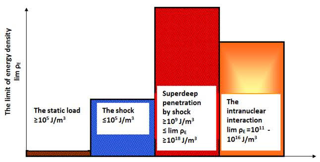
Figure 1 .The diagram of density of energy of various processes depending on speed of interacting installation for SDP treatment
Membrane technology is a rapidly growing field having a large economic and ecological consequences and importance. As well know track membranes are more effective [2].
A track mem¬brane is a thin polymer film with through pores which are formed by penetrating a special substance into and through the material of a polymer plate and then removing the traces of penetrated particles from the matrix material thus forming pores. The track membrane may find use in various fields of industry as conventional membrane filters for purification of liquid substances from solid contaminants. In view of low manufacturing cost and only a slight deviation of the holes from the rated diameter (within the limits of 10 to 20%), the track membrane of the invention may be advantageously used as a dialysis filter.
A multitude of straight openings pores in sheets of polymeric materials, formed by homogeneously bombarding the sheet with a source of heavy energetic charge particles to produce damage tracks as have been described in [3] On subsequent stages radiation damaged materials are removed by chemically etching as by immersing the irradiated solid in an etchant. Different chemical reagents (etchants) and etching methods are known as a rule as etchants are used the alkali solution. Without of destroyed materials as produced by high toxic solvents. Its makes the industrial methods of track membrane production non ecological and less technological. Besides, these methods demand the usage of expansive nuclear reactor or accelerates, for example, the cyclotrons.
At the same time, there are various methods of treatment of different materials and products, including polymers, with the use of explosive energy. For example [4], discloses a treatment of synthetic polymeric materials by contacting end¬less sheet-like, ribbon-shaped or filiform polymeric products with 0.1 to 2 mm size particles of sand, glass, corundum or a metal by directing onto the surface a stream of gas carrying the aforesaid particles. This gives the textile structures a rough, woolly, soft feel and they are mat, while films become rough and mat and have a low transparency.
The advantages of track membranes such as high pores density and uncial selection combined with combine with negative factors, for examples, high absorption activity [5].
According to this the great scientific and practical interest has the use for track membrane production the method of super deep penetration (SDP) [6]. This So we can propose the possibility of SDP method use for making of open pores in polymer matrix.
The method of SDP is carried out by using a matrix material of the membrane and special working substances which interact with the matrix in the form of a high-speed jet generated and energized by an explosion of explosive material [7]
The special working substance comprises a saturated or supersaturated aqueous solution of water soluble organic salts, or a saturated or supersaturated aqueous solution of water soluble inorganic salts. The organic salts are selected from the group comprising tartrates, acetates, salicylates, benzoates of alkali metals, for example potassium tartrate, sodium acetate, sodium salicylate. The inorganic salts are selected from the group comprising halides of the alkali met¬als and alkaline earth metals, for example sodium chloride, sodium bromide, potassium fluoride, calcium chloride.
The matrix material comprises an organic polymer material in the form of a solid plate.
As a polymer matrix we can use polyolefin (poly¬ethylene, polypropylene, etc.), polyvinylchloride, fluorinated polyolefin (polytetrafluoroethylene, polyvinylidene fluoride, etc.), polyamide, polycarbonate, polyester, polysulfone, etc.
A device for realization of method comprises a shell in the form of a tube one end of which contains a cartridge with an explosive material and working substance in the form of a solution of solid water-soluble salt or salts. Inserted freely into the other end of the shell is a holder that contains a membrane matrix to be treated in the form of a plate. The open end of the holder is closed by a cover which is attached to the holder, e. g. by screws, whereby the membrane matrix is secured in the holder. The shell with the cartridge that contains the explosive material and the working substance as well as the holder with the matrix of the material to be treated is placed into an explosion-proof chamber, and the explosive material is detonated to cause and explosion.
As a result, the working substance is expelled from the cartridge by an explosive wave in the form of a high-speed jet and penetrates deep into and through the polymer material of the plate. Under the effect of the explosion, the holder with the polymer plate and cover is ejected from the shell into the explosion-proof chamber. The cover is disconnected from the holder, the matrix is extracted, and is subjected to treatments with water that dissolves the water-soluble particles or wash them out from the membrane matrix thus forming microscopic openings that pass through the polymer plate. Then the polymer plate is sliced into thin pieces that can be used, e. g., as filter plates. For tracking membrane production by SDP method it is necessary to optimize the following parameters:
the chamber size,
type and charge construction,
the explosion power,
the velocity of detonation,
the thickness of charge,
the type and dispersion of working substance,
the distance from charge end till polymer sample,
the solvents composition ,
the material and the size of screen and etc.
So we optimize the above mentioned parameters of explosion chamber, which provide the demanded quality of tracking membranes. As a first step we choose the conditions of preservation of the sample during bombardment. The parameters of explosion chamber used previously for creation of open pores in ceramics matrix cannot be usage due to the difference of elasticity modules of polymer material and ceramics. So we have produced the special protective steel screen with one central and several scattered holes. It provides the part of impact wave energy consumption for destruction of the steel screen.
For preservation of polymer sample during bombardment was produced special steel container with hole in the bottom during which the particles of working substances penetrate into polymer matrix as a charge was used the ammonite of bulk density 0.8-0.9 g/sm3 ( Fig.2).
The device contains the a tubular plastic shell with both open ends. The height of plastic tube is 200 mm. The device contains a cartridge with the detonatable explosive material and the working substance in the form of a supersaturated solution of water-soluble solid salt. The cartridge is inserted into lower open end of the tubular holder. Detonator is used for detonation of the explosive material. The membrane holder with an open-bottom cavity for receiving a membrane matrix is inserted into the upper open of the shell. The device is placed into an explosion-proof chamber.
The explosion wave that has a detonating nature should impart to the solid particles of the working substance a velocity in the range of 3800 to 4200 m/sec.
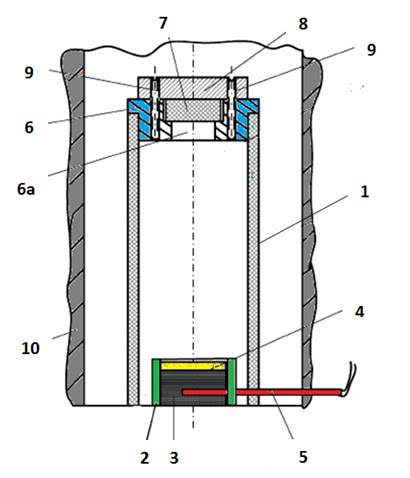
Figure 2. Vertical view of constructed device for membrane production by SDP method. 1- tubular shell; 2- cartridge; 3- detonatable explosive material; 4- supersaturated solution of water-soluble solid salt; 5- detonator; 6-membrane holder; 7- cavity of the holder; 8- cover of the holder; 9-fasteners; 10- explosion-proof chamber [7]
Some particles deeply penetrate into the membrane matrix material and some par¬ticles pierce the body of the membrane matrix from its exposed side. Under the effect of the explosive wave, the holder together with the membrane matrix and the cover are expelled from the shell into the explosion- proof chamber . The cover is then disconnected from the holder and the treated membrane matrix is extracted from the holder 30. However, the membrane matrix will still contain residue of the water-soluble particles of the work¬ing substance. Removal of the residual trace particles of the solid substance from the membrane may be carried out in the running flow of water, leaving a pluraly of small-diameter holes. As a polymer matrix firstly we use impact strength polyethylene. At the same time perspective materials for production of polymer membranes by SDP method are polyethyleneterephthalate, polycarbonate and etc.
The solid plate of matrix polymer materials may have a total thickness in the range of 10 to 20 mm. After removal of the residue of the working substance, the solid plate is sliced into track membrane shaving a thickness of 5 to 50 µm by means of a microtome.
The microstucture of prodused by SDP method membranes is presented in Fig.3.
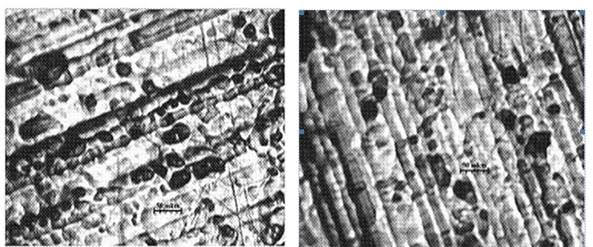
Figure 3. The electronic microscope pictures structure of nanomembranes based on polyethylene.
The picture show section of samples taken parallel to the diameter of the polymeric cylindrec by means of microtome. The black dots in the photographs represent the pores of the sliced samples, which have the size in the range of diameters of 80-100 nm
The actual diameters and the range of the diameters of the holes depend mainly on the velocity of the particles, diameter of the shell, and a distance from the cartridge with the explosive material and the particles to the membrane matrix material in the holder. The through holes produced in the track membrane are oriented in the direction of the jet of particles and occupy from 10 to 20 vol. % of the membrane material volume.
The main drawback of the SDP method of polymer tracking membranes production is its very design, i.e., all the risks associated with the use of explosives. The method cannot provide uniformity in distribution of distribution of track holes and their diameters. Another significant disadvantage of the explosion method is a reflected wave upon detonation. At the same time the shock wave is reflected from the shell and moves to the center carrying with it a significant part of the energy, while the pressure around the shell rapidly falls off (faster than instantaneous detonation). As a result, the acceleration of the shell is reduced more rapidly than with instantaneous detonation. This significantly reduces the efficiency of the explosive impact on the membrane matrix.
New method for treating thin-film materials with a flow of solid particles in an electric field is developed [8]. More specifically, the method for manufacturing track membranes is based on piercing a matrix of a thin-film material with a flow of hard particles generated by an electric field. The essence of the method consists of charging and accelerating particles of a powder that constitutes a working material for treating, e.g., perforating a thin-film object intended for manufacturing, e.g., track membrane for use as membranes for dialysis, filtering gases, etc. The particles are accelerated and acquire a kinetic energy under the effect of an electric field developed between two metallic electrode such as a continuous charging electrode and a perforated electrode, e.g. in the form of a net. The object being treated may comprise a replaceable thin-film sheet or a belt periodically shifted and fixed in a working position for exposure to the action of the moving particles.
Realization of the method is based on the use of an apparatus that consists of a closed chamber which contains two mutually spaced and electrically separated metallic electrodes. One of the electrodes is an acceleration electrode in the form of a net with a plurality of openings or cells for passing the particles to the exposed object, while another electrode, which referred hereinafter as a charging electrode, is continuous.
The method is carried out as follows. First, a specific powder of a selected material, shape, and size is supplied to the inter-electrode space by means of the powder supply unit or injector. Next, a voltage CV is supplied to the metallic electrodes. A part of the powder particles should already have a non-compensated charge but neutral particles will acquire the non-compensated charge under the effect of the electric field. As a result, under the effect of the electric field EF, which is generated between the electrodes in the inter-electrode space, the charged particles begin to move with acceleration to the acceleration electrode. and, when reach this electrode, the particles develop a significant kinetic energy that depends on the value of the charge, particle mass, and potential difference between the electrodes.
Realization of the proposed method is based on the use of an apparatus that consists of a closed chamber that contains two mutually spaced and electrically separated metallic electrodes. One of the electrodes has a plurality of openings, e.g., cells, if this electrode is a net; another electrode is continuous. The apparatus is provided with a powder supply mechanism or injector for the supply of a specific powder into the inter-electrode space formed between the electrodes, preferably closer to the continuous electrode[
First, a specific powder of a selected material, shape, and size is supplied to the inter-electrode space by means of the powder supply mechanism or injector. Next, a voltage is supplied to the metallic electrodes. A part of the powder particles should already have a non-compensated charge but neutral particles will acquire the non-compensated charge under the effect of the electric field. As a result, under the effect of the electric field the charged particles begin to move with acceleration to the net-like acceleration electrode. and, when reach this electrode, the particles develop a significant kinetic energy that depends on the value of the charge, particle mass, and potential difference between the electrodes.
More specifically, the particle charge can be evaluated by the following equation:
Q=ε_0 AE ,
(1)
where: Q is a dust particle charge; ε_0 is dielectric permeability of vacuum; A is a surface area of the particles; and E is an intensity of the external electric field.
A charge article experiences an effect of the electric field, and when the electric force is greater than the weight of the particle, the latter may levitate. The value of this critical electric field E_c is evaluated from balance of forces in the following manner:
mg=ε_0 AE_c^2 , (2)
where: m is a mass of a dust particle, and g is acceleration of gravity. For a spherical particle a value of the critical electric field is equal to
〖 E〗_c=√(ρdg/(6ε_0 )) , (3)
where: ρ is a density of the particle material; and d is a particle diameter.
Fig.4. shows theoretical and experimental values of a critical electric field for various solid materials. Particles used in the experiments had a cubical or spherical shapes, and the dimensions of cubical particles were recalculated to diameters of spherical particles of the same surface area. It can be seen from Fig.4. that the measurement data and the theoretical data correspond each other.
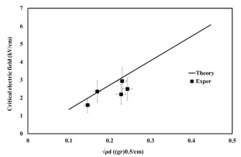
Figure 4.. Theoretical and experimental values of a critical electric field for various solid materials
When the intensity of the electric field is higher than its critical value for the given particle type, the particles are accelerated. If the friction forces are neglected, the pulse equation can be written as follows:
m dυ/dt=ε_0 AE^2-mg , (4)
where: υ is a velocity of the charged solid particle
.
A charged particle is accelerated by the electric field in the direction opposite to the direction of the gravity force. If we assume that the electric force intensity U=El is constant on the entire way of particle acceleration between two electrodes, the accumulated kinetic energy acquired by the particle can be expresses by the following equation:
K=(ε_0 A〖U/l^2 〗^2-mg)l , (5)
where: l is the acceleration path, and U is the applied field intensity between the electrodes.
When the particle is accelerated particle collides with the material of the membrane, the particle may be reflected from the surface of the membrane or may penetrate into the material, leaving a trail of the material in the form of pores — track. The geometry of the pores formed corresponds to the flight path of the particle within the material. The kinetic energy of the accelerated by the electric field of particulate matter is converted into energy of destruction of the material. It is assumed that the hardness of the material particles is much greater than the hardness of the membrane material, and energy is not spent on the destruction of the particles themselves. For particles with a size comparable to the thickness of the bulk material (membrane material), the material may be destroyed when the brake force of inertia balanced c destructive power.
The conducted experiments show the fact that in an electric field a solid particle can be charged and that its movement can be accelerated is experimentally observed is a phenomenon that can be used as a basis for developing various devices and processes.
When the accelerated particle collides with the material of the membrane, the particle may be reflected from the surface of the membrane or may penetrate into the material, leaving in the material a trail in the form of a pore known as a track. The geometry of the pores formed corresponds to the flight path of the particles within the material . The kinetic energy of a particle accelerated by the electric field is converted into energy of destruction of the material [9].
Let us assume that the hardness of the material particles is much greater than the hardness of the membrane material and that the energy is not spent on the destruction of the particle itself. For particles with a size comparable to the thickness of the bulk material (membrane material), the material may be destroyed when the brake force of inertia is in balance with the destructive power. Thus, the critical condition can be written as follows:
ma=Sσ , (6)
where: a is an acceleration of a solid particle in the membrane material S is a cross-sectional area of the destruction. In the condition expressed by equation (6), the friction force between the solid particle and the membrane material is neglected.
If it is assumed that on the other side of the membrane (i.e., on the side opposite to the bombarded side) the velocity of the particle is equal to 0), then the acceleration of the particle can be expressed as follows:
a=(υ_0^2)/2h , (7)
where: υ_0 is a velocity of the solid particle after acceleration in the electric field; and h is a thickness of the membrane.
The destruction area can be expressed a follows:
S =Lh (8)
where : L is a total length of the destruction. For a spherical solid particle the total length of the destruction can be expressed by the following formula:
L=n d/2 , (9)
where n is a destruction number. The value of the destruction number “n is dimensionless and can be obtained experimentally. In other words, when a solid particle that moves with a high velocity passes through a thin film and makes hole in it, such a hole is normally surrounded by a number of thin cracks that extend radially outward from the periphery of the formed hole. The applicants decided to evaluate the destruction number n as a ratio of total length of such cracks to the radius of the hole formed in the thin-film material. Normally the destruction number n is in the range of 3 to 6 and the final value is calculated as an average value, e.g., from 10 to 20 measurements.
By using The value of the destruction number n is dimensionless and can be obtained experimentally. In other words, when a solid particle that moves with a high velocity passes through a thin film and makes hole in it, such a hole is normally surrounded by a number of thin cracks that extend radially outward from equation (12), the upper limit of the membrane thickness can be determined from the following equation:
h=√((ε_0 A(U⁄l)^2-mg)l/σL), (10)
For spherical particles, the formula for the membrane thickness can be converted into the following expression :
〖 h〗_s=√(πld(〖6ε〗_0 (U⁄l)^2-ρdg)/3σn), (11)
Calculation by means of the upper limit of the membrane thickness by using formula (11) for a spherical particle of aluminum oxide (having diameter d=10-4 and density ρ=3200 kg/m3) accelerated in the electric field generated by the potential difference U=6000 V at the inter-electrode distance l=0.02 m, for a strength limit of the membrane material σ=106 Pa, and a destruction number n=3, gave the upper limit of the membrane thickness at which the membrane could be pierced with the formation of through openings equal to h_s≈10-6m.
Realization of the proposed method is based on the use of an apparatus (Fig.5).
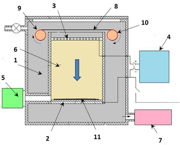
Figure 5. Apparatus for production of tracking membranes by accelerated particles of powders: 1- Chamber (L= 100 mm , W= 30 mm . H= 100 mm); 2,3- Electrodes; 4- Voltage power; 5- Powder injector; 6- Inter-electrode space; 7- Vacuum pump; 8- Film: 9, 10 – Bobbins; 11- Specific powder
The apparatus consists of a closed chamber (1) that contains two mutually spaced and electrically separated metallic electrodes (2) and (3). Acceleration electrode (3) is a net , has a plurality of openings, another charging electrode (2) is continuous . The apparatus 100 is provided with an adjustable high voltage power supply unit (4) for the supply of CV to the electrodes and a powder supply unit or injector (5) the supply of a specific powder into the inter-electrode space (6). The apparatus may be equipped with a vacuum pump (7) for evacuation of air from the interior of the and with a device for injection of inert gas into the space (6). A thin film material (8) which in Figure 48 is shown as a continuous belt moveable from the supply bobbin (9) to the receiving bobbin (10), is located over the acceleration electrode (2).
The process of production of tracking membranes is describe d below.
Solid particles which in the inter-electrode space (6) are loaded onto the charging electrode (2) acquire a charge which in its sign corresponds to the sign of the charging electrode. Under the effect of the electric field, the particles start moving towards the accelerating electrode (3) which bears the charge reverse to the charging electrode. As a result, solids particles of the powder are accelerated by the electric field generated between the charging and accelerating electrodes. The powder particles pass through the open cells of the net and impact the thin-film material (8).
The exposure time τ (s) is determined by the intensity J_m (kg/(m^2 sec)) of the particle stream at the output from the inter-electrode space and by the desired density of holes σ (m^(-2) ) in the membrane to be produced. The exposure time τ (s) is calculated by means of the following formula:
τ=(σρk_f D^3)/J_m (19)
where: ρ is a density of particle material, k_f is a coefficient that depends on the shape of particles, and D is an average side of the particles.
Conclusion.
The SDP method opens the great perspectives for production of tracking membranes based on polymer matrix. This method is cheaper, more simple and ecological friendly as compared to nuclear industrial methods . It’s use excludes the application of high toxic solvents. Simultaneously it permits to create of polymer membrane with micro and -nanosize open pores and besides provides the absence of oxidation products, which can migrate into filtrate.
New method for manufacturing track membranes by piercing a matrix of a thin-film material with a flow of hard particles generated by an electric field is proposed. The essence of the method consists of charging and accelerating particles of a powder that constitutes a working material for treating, e.g., perforating a thin-film object intended for manufacturing, e.g., track membrane for use as membranes for dialysis, filtering gases, etc.
REFERENCES
Figovsky O, Beilin D., Usherenko S., Kudryavtsev P (2016), Environmental friendly method of production of nanocomposites and nanomembranes J. Scientific Israel- Technological Advantages vol.18, № 2
Apel P. Track etching technique in membrane Technology. Radiation Measurements. №34, 2001. Pp/ 559-
Usherenko S., Figovsky O.,(2008) Novel Environment Friendly Method of Preparing Nanoreinforced Composites Based on Metallic,s Ceramic and Polymer Matrixes- Superdeep Penetration, Silicon Versus Carbon, Proceeding of the NATO Advanced Research Workshop on Environmental and Biological Risks of Hybrid Organic-Silicon Nanodevices, St. Petersburg, Russia, 18-20 June 2008. pp.31-54
Figovsky O., Gotlib E., et.al. (2012)Super Deep Penetration — new method of nanoreinforced composites producing based on polymer matrixes, J. Scientific Israel- Technological Advantages, Vol.14, no 1, pp. 74-78.
E., Figovsky O., et al., (2011) Influence of mixing method of modified wollastonite with rubbers based on SRI-3 on their structure,. Newsletter of the Kazan State Technological University. No 15, pp. 141-145.
Figovsky O., Usherenko S., (2009_) Composite materials prepared by SDP-Method: the physics of superdeep penetration, Nanotechnics, No. 3(19), pp.27-37. (in Russian).
Figovsky O., et.al. Method of manufacturing a track membrane. US Patent № 8980148, 2015.
Kudryavtsev. P., Figovsky O. METHOD AND APPARATUS FOR MANUFACTURING MEMBRANES BY PROCESSING THIN-FILM MATERIALS WITH A FLOW OF ELECTRICALLY CHARGED SOLID PARTICLES. US Patent application № 20180067023. 2018.
Figovsky O., Berlin D. Green Nanotechnology. Pan Stanford Publication. 2017. 539 p
Иллюстрация:


